Crossovers And Filters
Click here to return to the library.
A crossover is a component or a group of components which limit the frequencies that reach a speaker. If “separates” (subwoofers, woofers, midranges and/or tweeters) are used in a system, they should not receive a frequency range greater than their design limits. Crossovers would be utilized to limit the frequency range to each “separate”.
Diagram 1 - Crossover Description
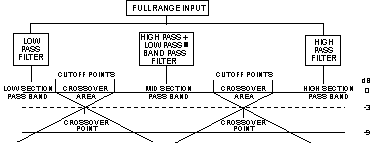
Crossover Points
The frequency range which a filter allows full power to pass through it is called the passband. The frequency at which a filter begins reducing power is referred to as the cutoff point. The range between two adjoining cutoff points is the crossover area.
As the frequencies move away from the passband area (starting at the cutoff point) power reduction increases. When it has reached 3dB in reduction, the crossover point has been reached.
All crossovers and filters are rated at their crossover point (or crossover frequency). This minus 3dB point is also known as the half power point.
There are two main types of crossover filters, the high pass, and the low pass. The high pass will pass high frequencies while restricting low frequencies. The low pass does just the opposite, in that it passes low frequencies while restricting high frequencies.
By combining a high pass and a low pass circuit in series, we create a band pass circuit, which allows a certain band of frequencies to pass, while restricting both high and low frequencies.
Diagram 2 - Crossover Slope

Slopes
Crossover filters may be constructed with different rates of reduction of power. Slope is the term used to describe this rate.
A 6dB per octave filter will reduce power by 6 dB in every octave starting at its cutoff point. For instance, a 6dB per octave low pass filter with a cutoff of 200 Hz would reduce power 9dB (6+3) at 400 Hz (200 times 2). At the end of the next octave, 800 Hz, an additional 6dB of power reduction would have been reached.
A 12dB per octave filter would have twice as much reduction per octave. An 18dB per octave filter would have three times as much reduction as a 6dB per octave filter.
If all frequency bands (low, mid, high) are at the same acoustical level, and the speakers for each section are receiving a frequency range well within their response capabilities, the slope of the crossover filter is not of great importance. On the other hand, if one section is at a much higher level than its adjoining section, or the range directed to a speaker is very close to its maximum range capabilities, or a great deal of power is received by a speaker, a steeper slope may be useful.
Diagram 3 - Acoustical imbalance
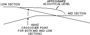
Diagram 3 shows a low frequency section which is much louder than the adjoining. This will occur when a much higher level is used for the low section than the mid section speaker.
The result is a bulge or broad peak in the combined acoustical output of the two sections at and above the crossover area. The crossover point, the slope, or both may be changed to correct the bulge.
A 6dB per octave filter will reduce power by 6 dB in every octave starting at its cutoff point. For instance, a 6dB per octave low pass filter with a cutoff of 200 Hz would reduce power 9dB (6+3) at 400 Hz (200 times 2). At the end of the next octave, 800 Hz, an additional 6dB of power reduction would have been reached.
A 12dB per octave filter would have twice as much reduction per octave. An 18dB per octave filter would have three times as much reduction as a 6dB per octave filter.
If a crossover point is close to the end of a speaker’s response range, the speaker may distort or not perform well in or near the crossover area. This problem can become critical as more power is applied or when more power is initially used in a system.
A steeper slope may solve this problem by reducing the power of lower frequencies more quickly. A faster rate of reduction (12dB per octave or higher) is used when a crossover frequency change is not desired.
As an example, a small midrange speaker may not perform well below 200 Hz, but for staging reasons, you do not wish to raise the woofers above 200 Hz. A faster rate of reduction with the high pass filter for the midrange may enable it to operate with a crossover point of 200 Hz.
The amount of power applied to a midrange (or tweeter) may shorten its useable range, especially low frequency response. As power is increased, the practical range of the speaker will compress. Consequently, where the same crossover points are used with 50 watts of power, they may not be acceptable at 100 watts of power. Changing crossover points and/or increasing the filter slope will enable the speaker to perform well without distortion.
6dB per octave passive filters are commonly used in mobile audio systems and operate quite satisfactorily. Crossover points should be well within the range of the speakers used. In addition, they cost half as much as 12dB per octave passives and one-third as much as 18dB per octave passive filters.
With tweeters, an 18dB per octave passive filter is advantageous as its greater slope adds some protection to this small and delicate speaker.
Electronic Crossovers
An electronic crossover operates at preamp level to limit the frequencies to the amplifier or amplifiers connected to it. The speakers which are connected to the amplifier(s) would therefore receive a limited frequency range.
It is a powered electronic circuit which limits or divides frequencies. The circuit operates independently and does not care about speaker impedance nor does it create any appreciable signal loss.
With active crossovers, the filters are built onto its circuit board. Changing the filters (or crossover points) is accomplished through external dial turning, by changing frequency modules with a switch or by changing crossovers if fixed types are used.
Active crossovers are usually 12dB per octave. There are some available which are 18dB per octave and higher. Generally, 12dB per octave is fine.
A crossover which has no crossover frequency adjustment is usually termed “Fixed Frequency”. Where crossover frequency changes are possible through a switch, knob or module change, they are called “adjustable” or “variable”. The advantage of fixed is cost; of variables, the ability to change crossover points with only one crossover model.
An adjustable crossover allows the user to make crossover changes easily and to immediately hear the effect of the changes.
Most electronic crossovers have output controls for each individual channel. This allows you to set the gains for all amplifiers at one convenient location, as well as the ability to “level match” a system.
Some crossovers will allow you to set the low and high pass filters separately, which allows you to “tune out” acoustic peaks or valleys at or near the crossover frequencies.
One of the advantages of electronic crossovers is that there is little or no insertion loss. Passives reduce the amplifier power slightly, due to their resistance.
Another advantage of electronic crossovers is the ability to separate low frequencies into their own exclusive amplifier, which reduces distortion heard at high volumes in the high frequency speakers. Amplification of low frequencies requires greater power than higher frequencies. When an amplifier is at or near peak output, clipping may occur, which is able to destroy tweeters and other speakers with small voice coils. A separate low frequency amplifier allows the total system to play louder and with lower distortion.
Passive Crossovers
A passive crossover filter is made exclusively with coils and/or capacitors. Passive filters are changed by using different coils and capacitors to obtain the crossover point desired.
A 6dB per octave low pass is simply a coil in series on the speaker lead. A 12dB per octave is a coil in series and a capacitor which is in parallel with the speaker. An 18dB per octave low pass filter is a coil in series, followed by a capacitor in parallel and another coil (of different value) in series.
A high pass circuit can be created in the same manner, except that wherever there is a coil, there is a capacitor and wherever there is a capacitor, there is a coil.
Diagrams 4,5 and 6 show the various low pass circuits.
Diagrams 7,8 and 9 show the various high pass circuits.
Diagram 4 - 6 dB Low Pass
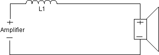
Diagram 5 - 12 dB Low Pass
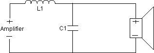
Diagram 6 - 18 dB Low Pass
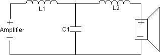
Diagram 7 - 6 dB High Pass
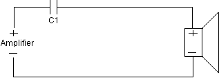
Diagram 8 - 12 dB High Pass
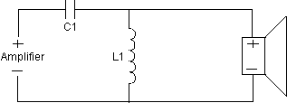
Diagram 9 - 18 dB High Pass
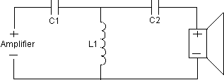
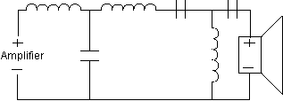
Band pass filters are a high pass filter and a low pass filter in series. Diagrams 10, 11, and 12 show 6,12 and 18dB per octave band pass filters.
Diagram 10 - 6 dB Band Pass
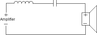
Diagram 11 - 12 dB Band Pass
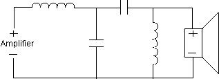
Diagram 12 - 18 dB Band Pass
One concept that is commonly misunderstood about crossovers, is that along with changing the acoustical response, the impedance is affected as well. What this means is that you can have a 4 ohm tweeter and a 4 ohm woofer, use a proper crossover, and create a 4 ohm load. It is very easy to make the mistake by thinking that it would create a 2 ohm load because of the drivers being in parallel.
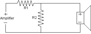
Diagram 13 - Attenuation Circuit
Attenuation
High frequency drivers are commonly more efficient than low frequency drivers. This creates a need to adjust the driver levels to create a uniform overall frequency response.
L-pads, which are the type described here, are the most suitable for adding to crossover circuits, because they do not change the resistive load shown to the crossover.
Diagram 13 depicts the wiring of an attenuation network.
Diagram 14 - Zobel Network

Zobel
All voice coil type drivers exhibit a rising impedance caused by the voice coil inductive reactance. In order for crossover circuits to operate properly, you can equalize this rising impedance by using the CR circuit shown in Diagram 14. You can also use this circuit for tweeter domes, not to facilitate network operation, but to help eliminate harshness, and to assure the accurate application of L-type shelving networks.
Diagram 15 - Series Notch Filter

Notch Filter
The primary function of the circuit illustrated in Diagram 15 is to dampen and eliminate the effects of driver resonance on crossover networks. Assuming the driver has an undamped resonance peak, and the peak is located less than two octaves from a high pass crosspoint, this circuit will greatly improve driver performance. It is particularly useful on tweeter domes, midrange domes, and cone type midrange drivers whose enclosure resonance is above 200 Hz.

