In order to install, design, or modify electronic devices in a car, a brief discussion of electricity and electronics background is necessary. The scope of this primer will be limited to real world application, and although far from being a course in Electrical Engineering, it will discuss all pertinent topics.
Electrons
Atoms are made up of three smaller particles: protons, electrons, and neutrons. Electrons have a unit negative charge, protons have a unit positive charge, and neutrons have no charge. Usually there are an equal number of protons and electrons in an atom yielding a net zero charge. When some kind of energy (electromagnetic, chemical, etc.) is applied, some of the electrons may be broken free, thus leaving an imbalance of protons and electrons in the atom. This will result in the atom having a net positive charge.
Current
The movement of free electrons from one atom to another is called current flow. Current always flows from negative to positive. A good analogy can be made with a water hose — the hose may be considered a conductor, and the water the moving electrons. The current, measured in amperes, would be the volume of water passing by a point along the hose in a given amount of time. The higher the volume, the more current.
Potential
For current to flow, there must be a potential difference between two objects. This potential difference is created from an excess of electrons at the source, and a lack of electrons, or positive charge, at the destination. Using the hose analogy, the potential difference, measured in volts, would be the pressure of the water within the hose. The higher the pressure, the more potential difference, and the higher the voltage.
It also can be shown that a larger hose can move a greater volume of water (more current) than a smaller hose. This corresponds to the size of the conductor. A wire conductor's size is called its gauge. The smaller the number, the heavier the gauge, and the larger the wire. Heavier gauge wire can conduct more current than a smaller gauge.
Resistance
Most all conductors exhibit a property called resistance. Resistance impedes the flow of current. It is measured in units called Ohms. Using the hose analogy, resistance can be regarded as friction between the water and the hose. A larger hose would create less friction and have a lower resistance than a smaller hose.
Power
Power is the amount of work done in a specified amount of time. The electrical unit of power is the Watt.
Ohm's Law & Watt's Law
George Ohm and James Watt created equations that allow us to mathematically express the relationship between current, voltage, resistance and power.
Since both formulas share current and voltage, you can substitute one into the other to derive all possible combinations:
AC / DC
In electronics, Direct Current (DC) means current always flows in one direction — like your vehicle's 12V battery supply. Alternating Current (AC) means the direction of flow reverses at regular intervals. In general, audio signals are AC, and battery voltage is DC.
Resistors
The resistor is a device that resists, or limits current flow. Their value is specified in ohms. A resistance to current flow creates heat, and as such, these devices have a maximum power dissipation, rated in watts. Placed in series with a voltage source, they limit current to a device. In parallel with a voltage source they make up a voltage divider. A potentiometer is a special type of resistor which, when the shaft is rotated, changes resistance via a sliding contact arm. They are used as volume controls, gain matching controls, etc.
If a circuit contains resistances in series, the total resistance is calculated by adding all the individual resistances:
Two 4-ohm speakers and one 8-ohm speaker in series:
4Ω + 4Ω + 8Ω = 16Ω total

Circuits that contain resistances in parallel are a bit more difficult to calculate. The formula involves reciprocals: the sum of the reciprocals of the individual resistances equals the reciprocal of the total resistance.
An 8-ohm speaker in parallel with a 4-ohm speaker:
1/8 + 1/4 = 1/RT
0.125 + 0.250 = 0.375
RT = 1 / 0.375 = 2.67 ohms

Capacitors
A capacitor is a device that resists change in voltage. It stores a charge. For our uses it will pass AC but not DC (while it is charging it will pass DC). Their value is expressed in Farads (or more commonly in microfarads). They have a working voltage (called DCWV) that must never be exceeded. They can be found in both polarized and nonpolarized versions. The most commonly used types are the electrolytic, mylar and poly (polypropylene, polystyrene, polyester). They are used primarily for filtration (in power supplies), noise suppression, and speaker crossovers.
For noise suppression, a capacitor is placed between the alternator, or component power lead, and ground. This will present an open circuit to the 12 volts DC once the cap is charged, but will provide a short circuit for the small AC "ripple". Polarized electrolytics are most commonly used. They are much cheaper than the other types, especially in larger values. A minimum of 25 DCWV is needed for safe operation in a 12 volt system.
Another use for the capacitor is in speaker crossovers. Although they pass AC, their impedance is inversely proportional with frequency. Placed in series with a speaker, it forms a 6dB/octave high-pass filter. A nonpolarized capacitor must be used.
Electrolytic caps are the cheapest for their size. If using electrolytics for crossovers be sure that the DCWV is at least 100 volts for amplified systems. Using a cap with too small of a working voltage will usually cause the cap to explode. Mylar caps are a bit more expensive than electrolytics of the same value, but offer higher reliability and sonic improvement. Metalized film poly caps are very expensive, but offer the highest sonic quality in critical listening applications.

Inductors
An inductor is a device which resists change in current flow. Usually it has a low DC resistance but a high AC impedance. This means that it passes DC well, but does not pass AC easily. It is electrically opposite to the capacitor. Its value is expressed in Henries (more commonly milliHenries). There are two major types of inductors, air core and iron core. The other important factor is the gauge of wire that is used to make the inductor. The heavier the gauge, the less signal loss and the higher the current capability.
For a given value and wire gauge, air core inductors are more expensive, but they offer some benefits. The greater the current flowing through an inductor, the larger the magnetic field produced. With iron core inductors, there is a point where the core saturates and no greater field may be produced. At this point, severe distortion sets in. Air core inductors for the most part do not exhibit saturation.
An inductor's impedance is proportional to frequency. They are used in noise suppression and speaker crossovers. Placed in series with a speaker, it forms a 6dB/octave low pass filter. Placed in series with a component's B+ lead, they will suppress noise.
Semiconductors
A diode (or rectifier) is a semiconductor which allows current to flow in only one direction. It can be used to change (rectify) AC into DC. The two leads of a diode are labeled anode and cathode. A diode is said to be forward biased when its cathode is at least .7 volt more negative than its anode. Forward biasing a diode causes current to flow, and reverse biasing causes no current to flow. A rectifier's value is expressed in amps, and is the maximum forward current which the device can safely handle. The peak inverse voltage (PIV) is the highest voltage which can be present while the rectifier is reverse biased.
Transistors are semiconductor devices which either act as current amplifiers, voltage amplifiers, or switches. The two most often used in mobile electronics are the bipolar transistor and the metal oxide semiconductor field effect transistor (Mosfet). They act as "valves" where a small change in control current or voltage on the input yields a great change in current or voltage at the output.
The chief disadvantage to using bipolar transistors is thermal runaway. Thermal runaway is a characteristic of bipolar transistors which causes more current to flow when the transistor gets hot. As more current flows, more heat is dissipated allowing even more current to flow. This cycle continues until the transistor destroys itself.
Mosfets are more similar to vacuum tubes in operation than bipolar transistors. They are transconductance devices, which means that the input works on voltage only without the need for current. They have extremely high input impedances. Mosfets do not exhibit thermal runaway like bipolars do — when Mosfets get hot, they actually allow less current to flow.
Kirchhoff's Laws
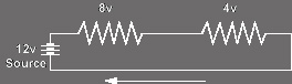
Kirchhoff's Voltage Law states that the sum of the voltage rises and drops in a closed loop circuit is zero.
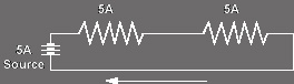
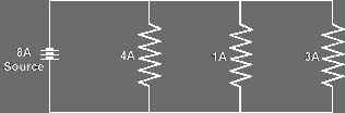
Kirchhoff's Current Law states that the sum of currents entering a junction must equal the sum of currents leaving a junction.
What this means is that in a series circuit the current flow through a circuit is the same at all points. With this in mind, we can determine the voltage drop across a resistance based upon the current and resistance.