Return to the library.
REMOTE TURN ON WIRE: What is it and how do I install it?
Whether installing on a car, truck, boat, UTV, or golf cart, one of the most common amplifier installation issues we troubleshoot involves the remote turn on wire. The remote turn on wire is responsible for turning your amplifier on and off.
This blue wire (typically with a white stripe), may be even more important to understand than your standard power and ground wires because if it isn’t installed correctly, your amplifier will not turn on even if it has good power and ground connections OR it may constantly draw power and drain your battery over night.
WHAT DOES THE REMOTE TURN ON WIRE DO?
The remote turn on wire receives voltage from the factory electrical system when the ignition is in the ACCESSORY or ON position (keep reading this document for the complete explanation). This voltage is transferred through the remote turn on wire to the amplifier turn on circuit; when the amplifier senses this voltage, it turns the amplifier on.
When the ignition of the vehicle is turned off, the remote turn on wire stops transferring voltage and the amplifier turns off.
If the remote turn on wire is connected to a wire in the vehicle that has constant voltage, the amplifier will always be on. If the remote turn on wire is connected to a wire that does not receive voltage when the ignition is in the ACCESSORY or ON position, the amplifier will not turn on until that wire does receive voltage.
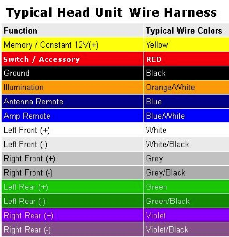
The blue/white stripe remote turn on wire has a number of other names such as accessory wire, system remote control wire, etc… Some of the confusion about this wire may come from the different wiring methods between a factory and an aftermarket head unit.
One thing to note, most head unit wiring harnesses also have a solid blue wire. This wire is typically for power antenna or factory amplifier turn on, do not get this wire confused with the remote turn on wire with the blue/white stripe.
AFTERMARKET HEAD UNIT
An aftermarket head unit typically has a clearly marked blue/white wire included in the wiring harness. Wiring the remote turn on wire with an aftermarket head unit is pretty straightforward. Simply connect another piece of blue primary wire to the blue wire in the wiring harness and run the primary wire back to the amplifier to terminate in the remote turn on terminal.
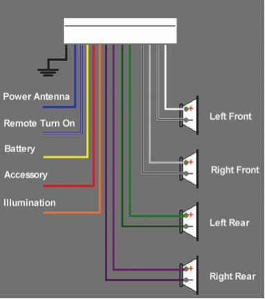
To connect wire to wire, an appropriately sized butt connector or other style connector can be used.
STOCK HEADUNIT
For stock head units, wiring the remote turn on wire isn’t quite as simple, but is still easily done if you follow the proper steps.
Since a stock/factory radio doesn’t have a remote turn on output like an aftermarket head unit, the voltage turn on signal has to come from the factory electrical system. The remote turn on wire must be connected to part of the vehicle's electrical system that only turns on when the ignition is in the ACCESSORY or ON position.
Some of the more common options for connecting the remote turn on wire when using a factory head unit are to the wire connected to a power antenna (older vehicles which do not turn off the antenna when not using the radio) or to the vehicle's fuse box. Since the remote turn on wire is low current, it can be connected to almost any fused output terminal (such as the one for the radio itself) as long as it only powers up when the vehicle is on.
(To make sure you choose a fuse that only receives voltage when the ignition is on, you can test with a multimeter before connecting the wire.)
Since the factory wire is already terminated on both ends, splicing into the wire is necessary. Use a T-tap connector or cut the factory wire to splice into the wire by twisting the remote turn on wire together with one end of the factory wire, then crimp on a butt connector. Next, reconnect the factory wire by inserting the other end into the open end of the butt connector and crimp. This will “tap into” the wire for the remote turn on but also reconnect the wire that was cut.
We recommend wrapping all butt connector connections in electrical tape or heat shrink.
WIRING REMOTE TURN ON TO A SWITCH
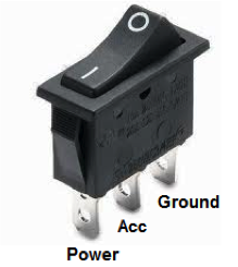
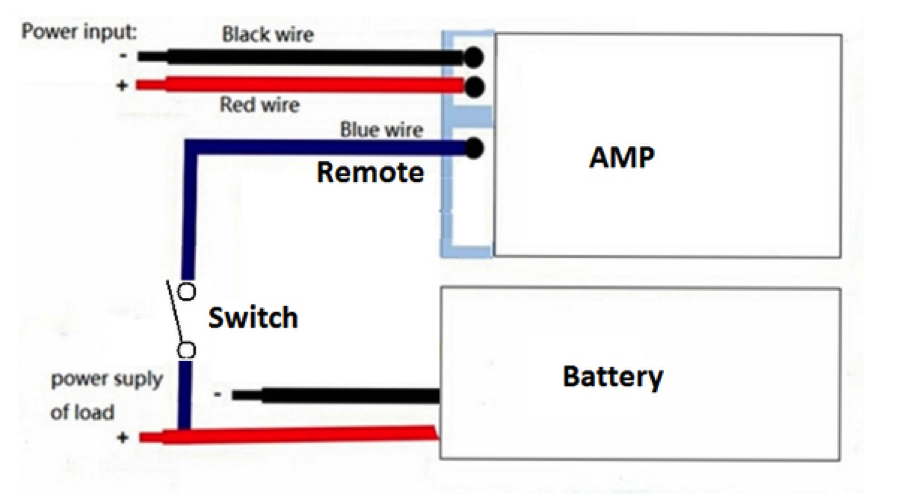
Another option for providing a proper remote turn on circuit is to wire constant power and ground to a switch and then wire the output of the switch to the amplifier's remote turn on. This way you can manually control when the amplifier turns on and off by the flip of a switch. The problem with wiring the remote turn on this way is if you forget to flip the switch to the OFF position, the amplifier will stay on creating a draw on the battery while the vehicle’s electrical system is not charging, which could result in a dead battery.
Wiring remote turn on to a switch is very common in off-road vehicle installations such as UTV’s, ATV’s, side by sides, etc...
TESTING YOUR REMOTE TURN ON WIRE
After your remote turn on wire is installed or if you ever experience any amplifier issues that are power related, you can easily test your remote turn on wire with a multimeter.
Just like you would test power and ground, you can test your remote turn on wire. With the ignition in the OFF position, place the positive lead of the multimeter on the end of the remote turn on wire and place the negative lead of the multimeter to a grounding point. Be sure the positive lead is touching the wire strands inside the jacket of the remote turn on wire.
With the ignition in the OFF position, there should be no voltage.
Then turn the ignition to the ON position and test the same way again. While in the ON position, there should be 12+ volts at the remote turn on wire.
If you have 12+ volts while the ignition is OFF, the remote turn on wire is connected to constant power.
If you don’t have any voltage while the ignition is ON, the remote turn on wire either doesn’t have a good connection or isn’t wired to something that receives voltage when the ignition is ON.
HOW TO SPLICE INTO EXISTING WIRING
When connecting (splicing in) to existing wiring for aftermarket installations, there are numerous methods available. We are going to talk about a few of the more common methods. The best way to splice into existing wiring is to solder every splice and then protect the bare wire connection with heat shrink and/or electrical tape. This method takes the longest and is the most expensive but tends to be the most durable connection. Other commonly used methods include using butt connectors and Scotch Locks. Butt connectors and t-taps are available in various sizes for various gauge wire. The different colors available reflect which size the connectors are.
Butt connectors (also called barrel connectors) are basically a metal tube wrapped in plastic insulation. To splice into a wire using a butt connector, you would cut the wire in the location where you want to install the butt connector. Then crimp one end of the wire you just cut into one end of the butt connector. Next, you would twist the new wire that you are installing to the other end of the cut wire. Then install the twisted end of the two wires into the other end of the butt connector and crimp this end as well.
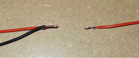
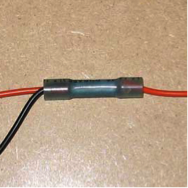
Wrapping the butt connector with electrical tape or heat shrink tubing protects the connection from moisture and other debris.
Scotch Locks tend to be a less dependable connection but they are very quick to install. They do not require cutting of the wire you want to splice into and the splice can be made with a single crimp.
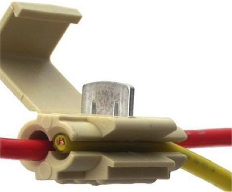
Scotch Locks use a metal “guillotine” that when pressed into the wires, cuts through the jacket of the wire to contact the wire strands and act as a conductor between the two wires.
Before pressing the “guillotine” into the wires, you first place the Scotch Lock around the wire you want to splice into. To do this, you slide the wire through the side opening and into the channel furthest from the opening. Then place the wire you are adding into the opening and inside the channel closest to the opening. Once you have the wires positioned correctly, start to close the top “latch” which forces the “guillotine” down through the wires and eventually locks onto the bottom part of the Scotch Locks.
When using Scotch Locks, we recommend testing the wire you just spliced to make sure the “guillotine” is making a good connection. Sometimes the “guillotine” doesn’t cut all the way through the insulated jacket and therefore doesn’t make a connection.
There are numerous styles of inline wire taps that could also be used; butt connectors and Scotch Locks are just two of the more common options.
THINGS YOU SHOULDN'T DO
Do NOT run a jumper wire from power to remote turn on:
One of the more common things we come across when troubleshooting amplifier installation problems related to remote turn on is when the amp will not turn on (often a result of not running a remote turn on wire at all or connecting it to a wire that doesn’t receive voltage when the ignition is in the ACCESSORY or ON position). An ill-advised solution is to run a jumper wire out of the power terminal into the remote turn on terminal.
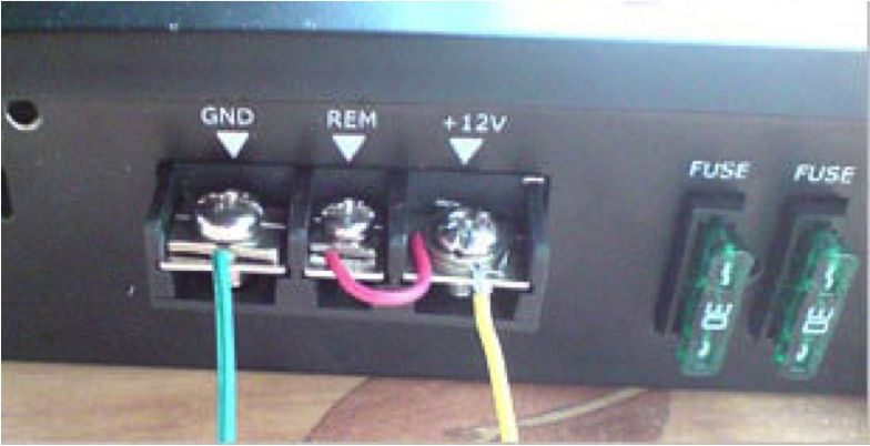
(Pic is just to show a jumper wire from power to remote turn on... You should never use primary wire for power and ground either)
Doing this will make the amplifier turn on, but it will never turn off because it will be receiving constant voltage. An amplifier that never turns off can create a draw on the battery resulting in the vehicle not being able to start if the battery is drained to a point it doesn’t have enough voltage to turn the starter.
Do NOT wire your remote turn on to power antenna in newer vehicles:
In older vehicles, wiring remote turn on to power antenna was very common and worked just fine because when the radio was on, the power antenna was up and working. But in newer vehicles, the power antenna may only be receiving power when the radio is in AM/FM mode. If you switch to Aux input, CD, satellite radio, etc… the power antenna wire will stop receiving power and your amplifier will power down as a result.
Understanding what a remote turn on wire does and installing it correctly will ensure there is no unwanted current draw on the vehicle’s battery when the audio system should be off. A little research to identify an appropriate factory wire to splice into for remote turn on will ensure the installation is done correctly and avoid wasted time troubleshooting this commonly made DIY mistake.
